Powersync
Communications Installation and Setup Instructions
877-459-4591
support@powersyncenergy.com
Manual Link: netorgft3957589.sharepoint.com/Shared Documents/Forms/AllItems.aspx?id=%2FShared Documents%2FLFP - Low Voltage Module%2FManuals%2FLFP-LV Module – Product Manual – POWERSYNC Energy Solutions 2022%2Epdf&parent=%2FShared Documents%2FLFP - Low Voltage Module%2FManuals&p=true&ga=1
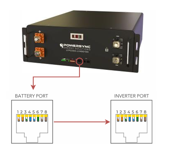
Custom RJ45 cable
No custom cable is needed.
BMS00
Connect the
master battery’s “CAN” port to the inverter’s “Battery CANBus” port (outdoor-rated only) or the “CAN” port (indoor-rated models).
Turn on Batteries
Turn on the batteries using the breaker labeled “Master Switch.”
BMS_Err_Stop
if you wish the system could fault on battery communications loss.

IMPORTANT NOTICE:
The battery module is NOT weight bearing and is not designed to support the weight of other battery modules. Do not place battery modules on top of one another without using proper racking or cabinet
solutions.
Battery Module Terminations
Battery Module Terminals Torque: Max of 7.5 Nm (5.5 ft/lbs)
There are two positive and two negative terminal connectors on the module. A 400A busbar connects the positive and the negative terminals on the inside of each
battery module.
Home Run Wiring
It is recommended to land the home run conductors in the following orientation.
It is recommended to land the home run conductors in the following orientation.
Battery Communication Wiring
The can-bus port on the HOST battery shall be connected with the corresponding connection to the CAN bus on the PCS/inverter (blue cable). There are two RS485 connectors on each module for module to module connections. When connecting the communications cables they shall be connected as seen by the black cables drawing in Figure 3. Continue down the string with alternating port connections.
Improper Connection Methods:
DO NOT REVERSE POLARITY BY CONNECTING POSITIVE TERMINALS TO NEGATIVE TERMINALS.
DO NOT CONNECT MODULE TO MODULE USING A SINGLE TERMINAL CONNECTION.
SINGLE MODULE THROUGH 8 MODULE INSTALLATION
NOTE: PRIOR TO THE INITIAL INSTALL, SET THE TOGGLE SWITCHES APPROPRIATELY
BEFORE TURNING ON THE BREAKER. WHEN ADDING MODULES TO AN EXISTING INSTALLATION, TURN OFF THE BREAKER, SET THE TOGGLE SWITCHES APPROPRIATELY, WAIT 20 SECONDS, TURN THE BREAKER ON.
NOTE: WITH THE 8-BIT LFP MODULES, DO NOT CONNECT MORE THAN 16 MODULES IN PARALLEL. IF YOU ANTICIPATE NEEDING MORE THAN 16 MODULES IN PARALLEL, USE ONLY THE 6-BIT LFP-LV MODULES
PRE-COMMISSIONING CHARGING
Battery may arrive at a low state of charge. It is a good practice to individually charge all batteries to a full charge using a 48V charger that is capable of CC/CV (Constant Current / Constant Voltage)
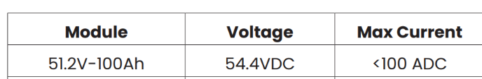
CHARGE VOLTAGE AND CURRENT
The Recommended Charge Voltage for the modules are as follows
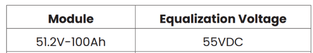
MULTI-MODULE EQUALIZATION RECOMMENDATION
MULTI-MODULE EQUALIZATION RECOMMENDATION
In circumstances where the modules are not able to get to a full charge for a few days, the modules may become slightly unbalanced. Over time the SOC of each module may drift. In order to mitigate these situations, Powersync recommends setting the battery system to perform an equalization for 60 minutes at least once every 7 days. The recommended voltage for the 60 minute equalization are as follows
Related Articles
Pylontech Pelio
https://pylonwebs3.s3.amazonaws.com/upload/2024/09/25/RESS-Installation%20Manual-Pelio%205PMPA08-00124_20240925122854A042.pdf Set the 'StartV' for the voltage at which charging should initiate. Float V = 55.7 V Absorption V = 56.0 V Equalization V = ...08/14/25 Endur Energy Integration Status
Endur Energy: Status Change EndurEnergy has been reclassified from "Certified" to "Proven" effective August 14th, 2025. Here is what that means, and what it does NOT mean: Do NOT tell customers Endur is no longer a partner. That is false. They will ...Residential Basic Programming Guide
BASIC PROGRAMMING GUIDE SYSTEM WORK MODES AND TIME OF USE FOR SINGLE INVERTER INSTALLATIONSDiscover
Notes You will need the Discover Lynk device to adapt the battery’s AEBus to CAN Bus for use with the Sol-Ark. The Lynk will need the proper adapter for the Sol-Ark’s pin configuration (Part number 950-0016-SLRK). Communications with this battery ...SOK
Notes Connect all batteries together with the provided RJ45 cables using the “RS485B/RS485C” ports. Either port can be used for each battery. Up to 15 batteries can be connected in parallel. Binary Numbering Set the DIP switches such that the battery ...