15K.11 Installation Workflow
Inspect Shipment
Upon delivery of materials, photograph the inverter box, showing any damage or list any missing components.
Upon delivery of materials, photograph the inverter box, showing any damage or list any missing components.
If damage or missing parts, immediately call +1 (972) 575-8875.
Other Useful Site Photographs
Other Useful Site Photographs
- Transmitter Dongle Serial Number
- DC wiring onto inverter
- Rapid shutdown device wiring
- Battery Setup Menu Tabs showing battery settings
- Lithium Battery Info Tab showing battery communication
- "Far Away" photo of the inverter wall and battery bank
Whole Home Backup
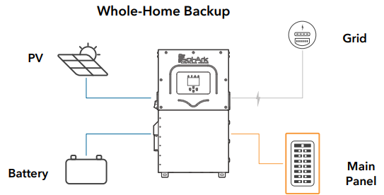
Connect the incoming grid directly to the “GRID” input terminal.
Connect the incoming grid directly to the “GRID” input terminal.
Connect the “LOAD” output to the Main Service Panel.
A single Sol-Ark inverter will pass a maximum of 200A max from the electric service, disconnect from the grid internally, and provide up to 15kW of AC output power to grid or load with solar power and 12kW of AC output power with batteries only.
AC nameplate capacity of the system = AC nameplate of inverter + AC nameplate of any AC-coupled solar.
Single Inverter Backup Capability → 15kWac = 240V * 62.5Aac continuous with solar and battery.
12kWac = 240V * 50Aac continuous with batteries only.
Standard Wiring Diagram
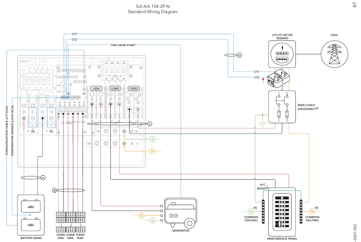
A typical Sol-Ark project includes a 200A external grid-side breaker in a box with CTs located after the disconnect.
The 15K is installed between the home and the grid, serving as the automatic grid disconnect.
Solar is DC-coupled to the Sol-Ark with or without a rapid shutdown system.
A 48V battery bank is added.
A generator or any AC solar is landed on the GEN port (disconnect required).
Included Items
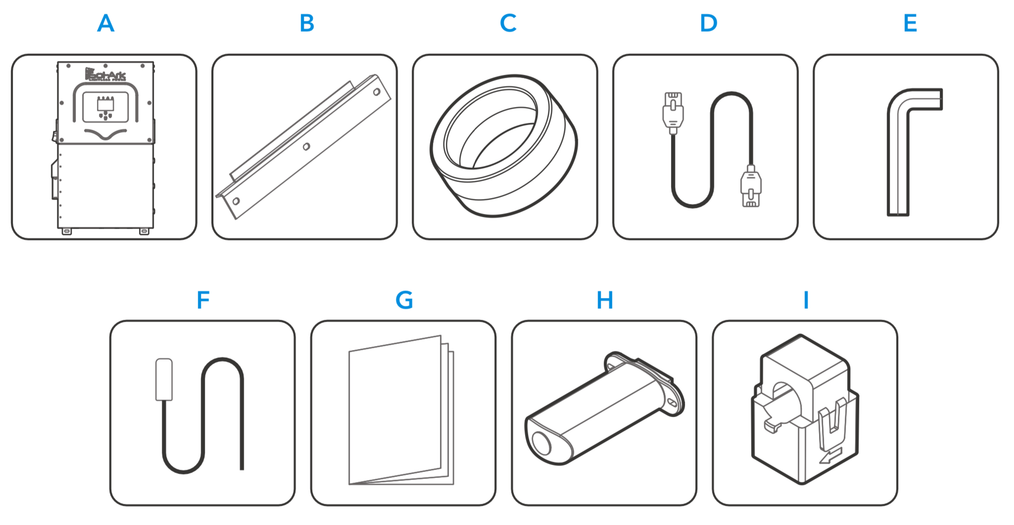
A. Sol-Ark 15K inverter
B. French cleat
C. Battery toroid x2
D. CAT5E comm cable
E. Allen key (4 mm)
F. Temperature sensor
G. User manual
H. Wi-Fi / Ethernet dongle
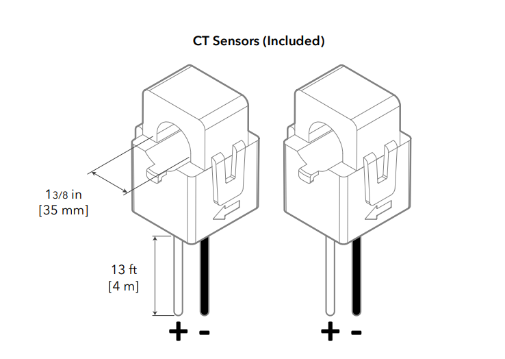
I. 1-3/8ths CT sensors x2
Not Included - External Disconnect Required for Grid Connection
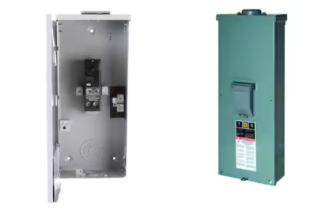
A service rated external grid disconnect with overcurrent protection (such as a 200A breaker in a box) must be installed between the grid and the inverter.
A disconnect is also required for any GEN port connection.
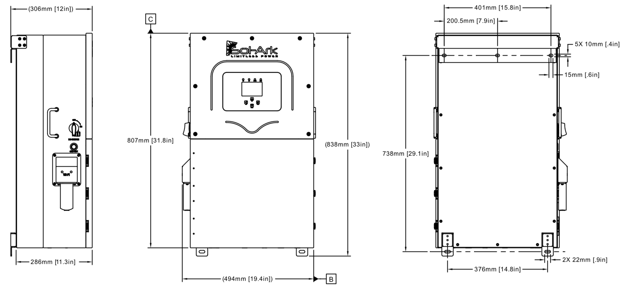
Dimensions
A service rated external grid disconnect with overcurrent protection (such as a 200A breaker in a box) must be installed between the grid and the inverter.
A disconnect is also required for any GEN port connection.
Dimensions
Wall Mount Fasteners Not Included (Bracket Included)
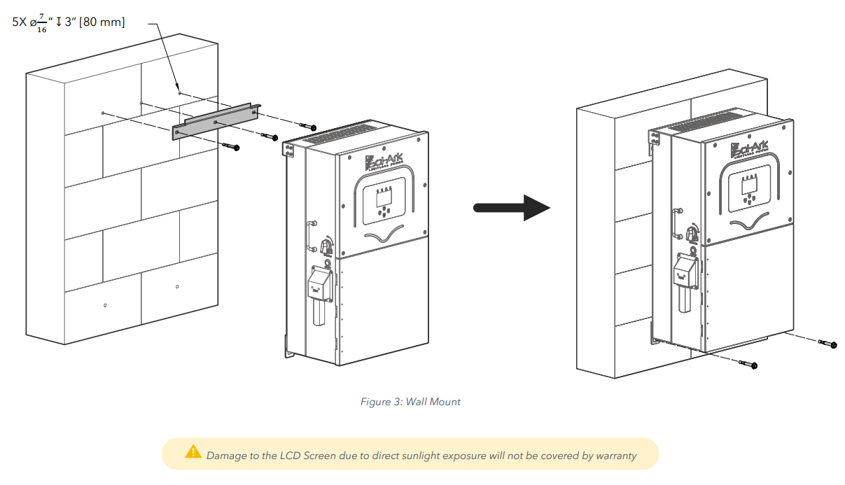
The wall mount bracket is included, however, the wall fasteners are not included.
Concrete or Masonry Mounting: Use a minimum of five (5) 3/8in expansion bolts
Metal Frame Mounting: Use a minimum of five (5) 1/4in self-tapping metal screws with flat washers. (not included)
For Wood Frame Mounting: Use a minimum of five (5) 3/8in lag screws with flat washers (not included)
Indoor / Outdoor Rating and UV Exposure
Sol-Ark 15K-2P-N is a NEMA 3R - IP65 enclosure that is rated for outdoor installation but can also be installed indoors.
The inverter weighs 135 lb / 61 kg.
Confirm the LCD screen is not directly exposure to UV light.
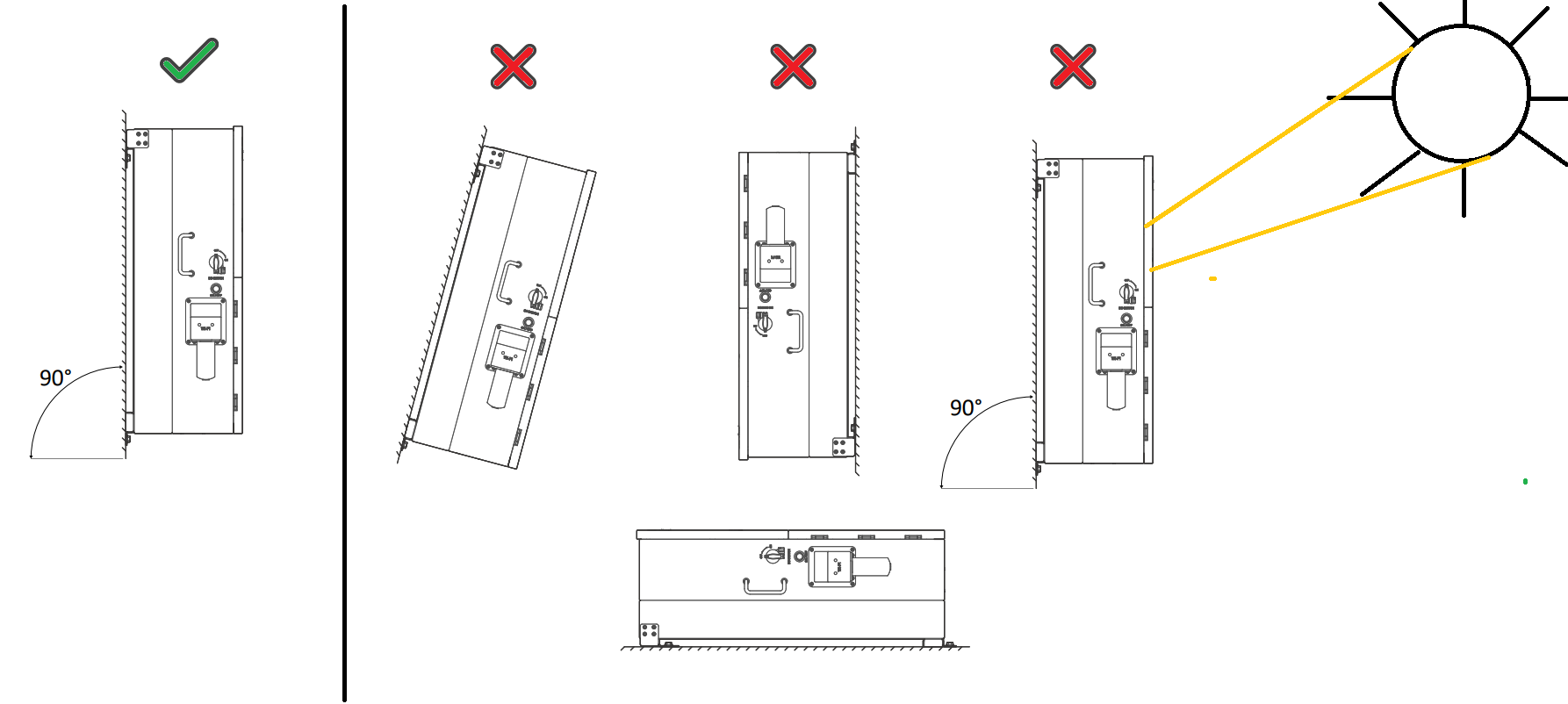
Mounting Instructions and Vertical Clearance
Confirm at least 6 inches [15 cm] of vertical clearance is given for proper heat dissipation.
Heat transfer and cooling is done from bottom to top at a rate of 525W/hr.
Mount the Sol-Ark and ensure the unit is level and properly seated.
Securely attach the inverter to the mounting surface. You may need expansion plugs or anchors for concrete.
When mounting to other surfaces or when mounting multiple pieces of equipment vertically, calculate the support needed to properly hold the weight of the equipment.
Knockout Details
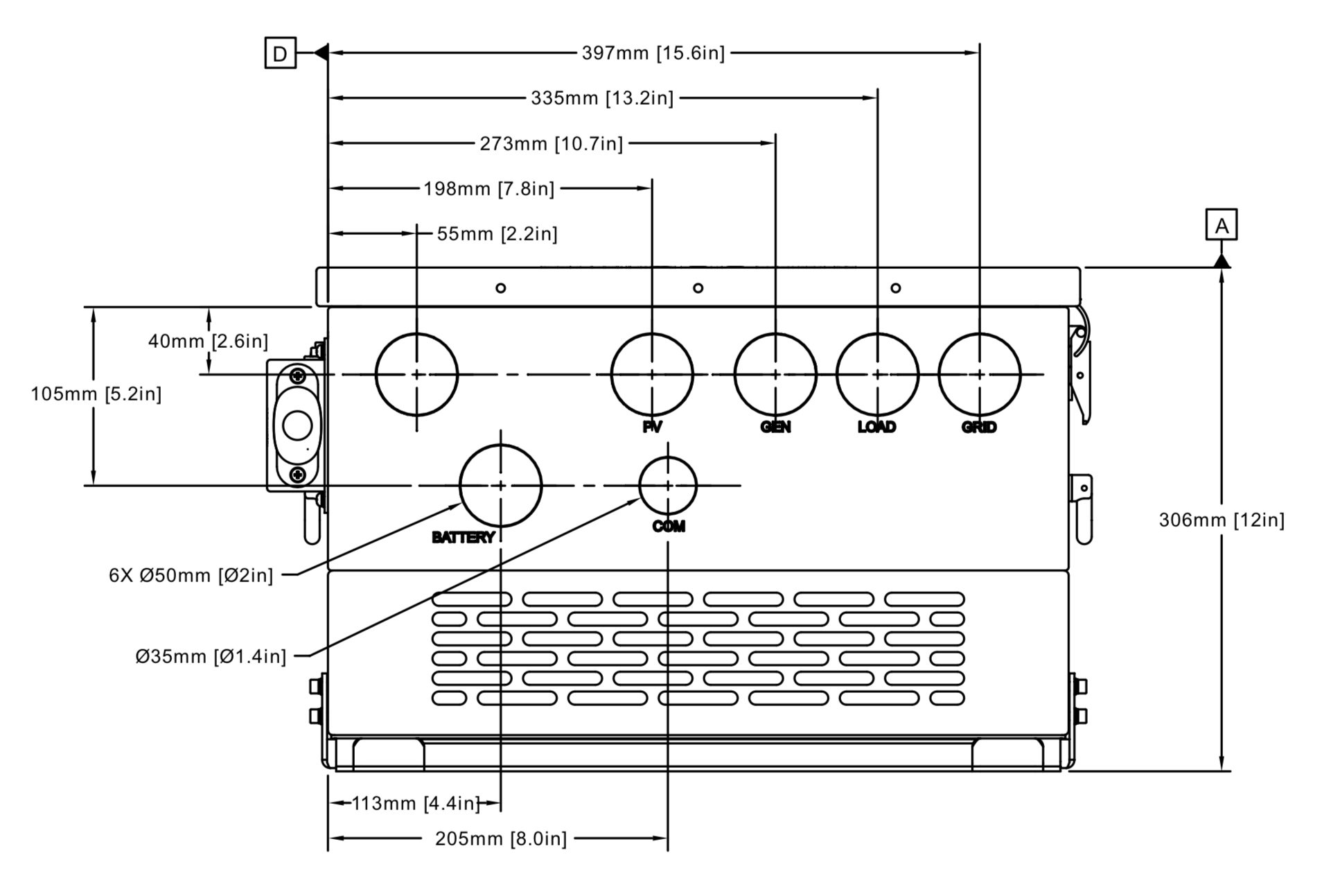
You may use a hydraulic punch to increase knockout sizes.
Do not use any other kind of tool to punch holes in the inverter chassis (ex. hole saws).
You must use conduit or double insulated wire for power conductors entering or exiting the inverter.
Torque Values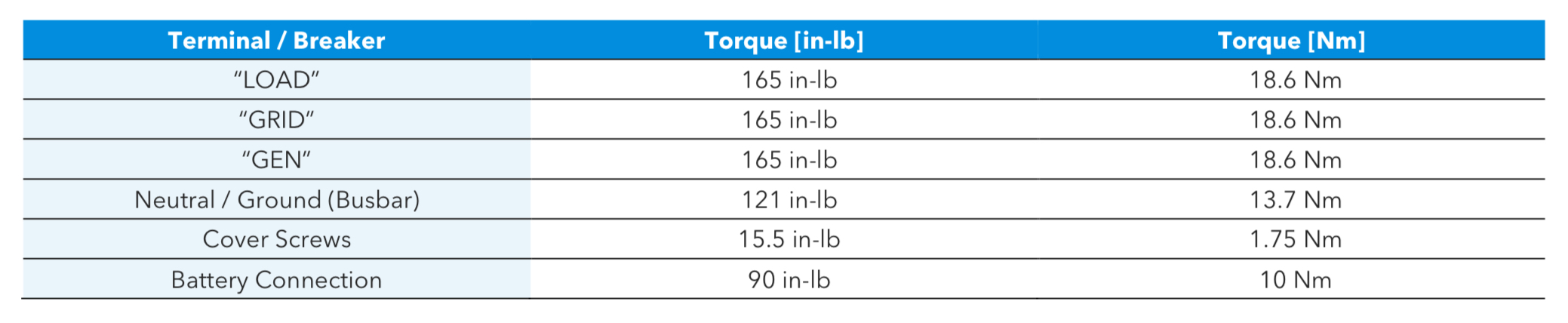
Do not use impact drivers to tighten any fasteners on the Sol-Ark.
Wire terminals are single conductor only.
Wiring Striping Guide
Grid and Load terminals must be between 1/0 to 4/0 stripped to 1" (not included).
Use ferrules when using fine stranded cable (not included).
Pay careful attention to strip wires to the correct length.
Aluminum is allowed on Grid/Load terminals.
Check voltage drop when batteries are >20ft from inverter.
Use #24AWG Sensor cable only within 30ft of inverter. Otherwise use #23AWG sensor cable up to 390 ft (120m) from inverter.
Note: Battery charger maximum amps is 275A. 4/0 cable is only always rated for 275A when in compliance with Table 400.5 NEC. Install per NEC. If installing conductor not rated for 275A, adjust maximum amp settings and lock user out of settings adjustment.
Use CTs to monitor the main electric service
The CT sensors help measure and calculate total building demand, including loads connected to the grid-side of the Sol-Ark GRID port.
By monitoring this demand the Sol-Ark 15K-2P-N can monitor and offset all existing loads without necessarily backing up the entire building.
This UL1741CRD Power Control System listing allows the Sol-Ark to current limit the output of the inverter, allowing load-side interconnections which would otherwise overload the AC busbar. For example, the Sol-Ark could interconnect on a 100A breaker on the load side of a 200A subpanel, providing 100A pass through to the subpanel, while maintaining the non-backup panel at 200A, so long as the total load does not exceed the capabilities of the system.
Regardless of residential or commercial application, CTs should monitor the entire grid side of the feeder circuit or circuits the system is intended to offset.
This improves monitoring accuracy when the inverter backs up the entire service, and enables offsetting non-backup panels too, useful in commercial design for example.
This monitoring is always tied to the master inverter.
On Multiple Inverter Installations, Only Wire CTs to Master Inverter
On Multiple Inverter Installations, Only Wire CTs to Master Inverter
CTs or any associated 3rd party modbus meters should only be wired to the master inverter.
The exception is when using the 15K in three-phase configuration, see 15k Three phase instructions.
The exception is when using the 15K in three-phase configuration, see 15k Three phase instructions.
CT Orientation
If grid-tied, CT sensors should be put around the main feed of the service unless otherwise instructed, using larger CTs if necessary.
If off-grid, CTs are not needed. Installers are instructed to pay careful attention to the directional arrow of the CT during installation.
If off-grid, CTs are not needed. Installers are instructed to pay careful attention to the directional arrow of the CT during installation.
Three phase or peak shaving CT sensor orientation have specific CT orientation instructions.
If the CT arrow is not visible, check the inside wall of the CT sensor.
Embossed arrows on the sensors must point towards the grid for residential installations except for the following circumstances:
If the system is 3Φ or grid peak shaving, point the arrows towards the inverter(s).
Wiring CTs leads to Inverter
Each inverter will include two (2) CT sensors which monitors the incoming grid conductors as a set.
Connect CT1 of line L1 to pins 3 (white) & 4 (black).
Connect CT2 of line L2 to pins 5 (white) & 6 (black).
CT Site Requirements
CT Sensors can be extended with CAT5E wire or better. Use shielded cable and use external communication conduit runs if at all possible.
CT Site Requirements
CT Sensors can be extended with CAT5E wire or better. Use shielded cable and use external communication conduit runs if at all possible.
Ordering Larger CTs
The Sol-Ark 15K-2P-N includes two 300A CT sensors (Ø1.378”). On 400 amp service or higher, or for some meter base combo design, special CTs are needed. Plan ahead and purchase these CTs directly from Sol-Ark. Contact the sales team for ordering, working with our field application engineers to pick the right CTs for your job. Visit shop.sol-ark.com/ or contact sales at +1 (972) 575-8875 / sales@sol-ark.com to purchase bigger CT sensors.
Default Sol-Ark CT ratio is 2000:1 on the 15K model unless authorized
DO NOT change CT Ratio or warranty will be voided
To ensure proper fit, check incoming wire diameters (grid or generator).

Warning
Sol-Ark 15K-2P-N and individual battery modules must be OFF while the batteries are being connected. If your battery bank does not have internal disconnects, maintain the necessary safety measures when installing.
Install - One Battery Stack
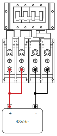
The 15K has a max battery charge/discharge of 275A when using both sets of battery terminals.
When combining to a single conductor not rated for 275A, set max amperage inverter setting appropriately and lock user out of system settings.
Install - Two Battery Stacks
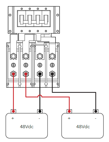
Use two battery stacks for easy 15K battery installation. The two battery ports act as an internal busbar and provide full use of the 275A charger rating at 160A max amps per port (200A OCPD).
Install - Two Battery Stacks
Use two battery stacks for easy 15K battery installation. The two battery ports act as an internal busbar and provide full use of the 275A charger rating at 160A max amps per port (200A OCPD).
Shared Battery Bank
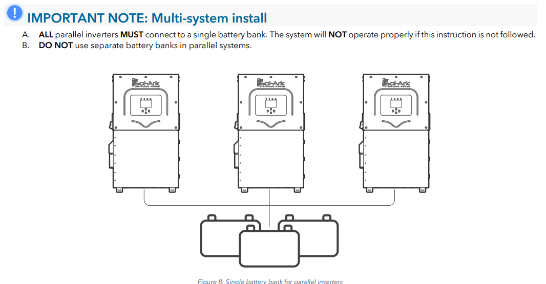
If using 3 or more batteries, use external busbars for (+) and (-) connections.
Batteries must be of the same brand, model, chemistry, and year connected to both terminals unless otherwise instructed by battery manufacturer.
Do not reverse battery wire
Make sure the positive battery conductor is clearly indicated at the battery and inverter and perform a polarity check before proceeding with commissioning.
Battery Torroid
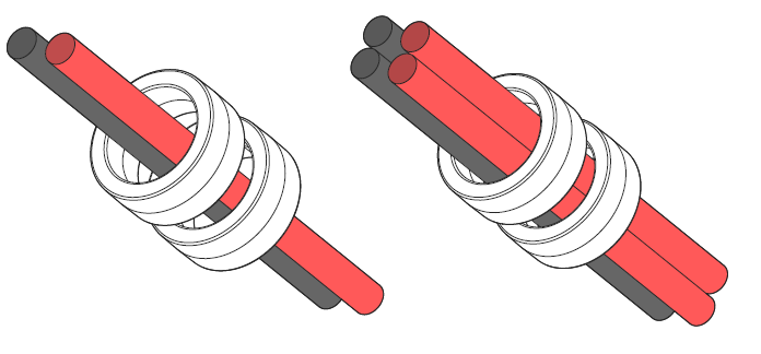
Install the included toroids on the battery home run conductors if at all possible.
Ensure that both (+) and (-) wires pass through both toroids simultaneously.
When four (4) wires present, all conductors must go through the torroids as shown.
Battery Temperature Sensor - Lead Acid Only
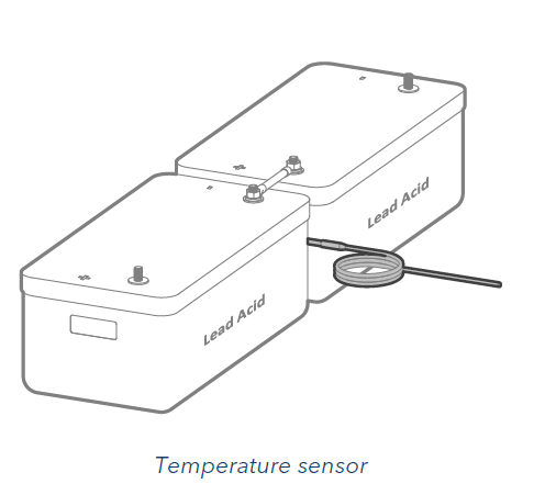
The battery temperature sensor is only used on lead acid batteries.
Lithium batteries should utilize battery <--> inverter communication instead or otherwise operate under conservative voltage settings consistent with battery manufacturer guidance.
Battery Communication Wiring
See 48V battery instructions for battery <--> inverter communication wiring.
String Sizing
Use our string sizing tool to confirm string size compatibility.
Enter approx solar array size in DC kW (STC nameplate)
The Sol-Ark 15K has 3 MPPTs with two wire ports per MPPT.
MPPTs can handle a maximum VOC of 500V and an
ISC of 44A but will self-limit and operate at 26A max.
Do not design the system to operate above 26A mid day.
Do not design the system to operate above 26A mid day.
Do not ground PV frame to inverter. Continue the ground forward.
Landing individual PV Strings onto Inverter
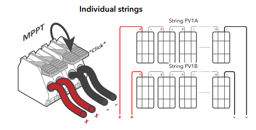
PV Strings sharing an MPPT should have same number of panels per DC string and face similar direction.
Landing Combined Strings onto Inverter
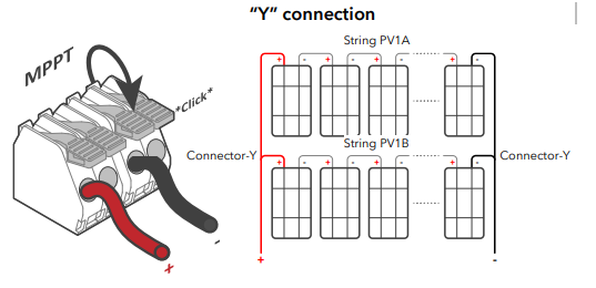
If combining PV circuits on roof, run pair of one home conductors to the inverter per MPPT.
Do not uncombine the home run and do not share home runs with between multiple MPPTs.
Solar on Multiple Inverters
Solar on Multiple Inverters
When DC coupling, evenly distribute the solar PV arrays across multiple inverters. If one inverter must have more solar than the others, make that inverter the master inverter.
Rapid Shutdown
USA Rooftop Markets require module level shutdown unless installing with a UL3741 listed RSD device.
The Sol-Ark provides a signal to an external rapid shutdown transmitter which triggers rapid shutdown functionality (not included).
Most MLPE options should derive their power from an AC power supply.
Emergency stop button connects to (B, B) pins of the Sol-Ark.
Do not install RSD external transmitters inside the Sol-Ark wiring box as it can cause interference.
Group PV Strings near shade objects onto their own MPPT.
Power RSD with AC Power (common)
It is common to power the external rapid shutdown transmitter through an AC power supply connected to the “LOAD” output.
Pressing the e-stop button will disconnect all AC outputs, cutting power to the “LOAD” service panel which will initiate rapid shutdown.
Powering RSD with DC Power (rare)wi
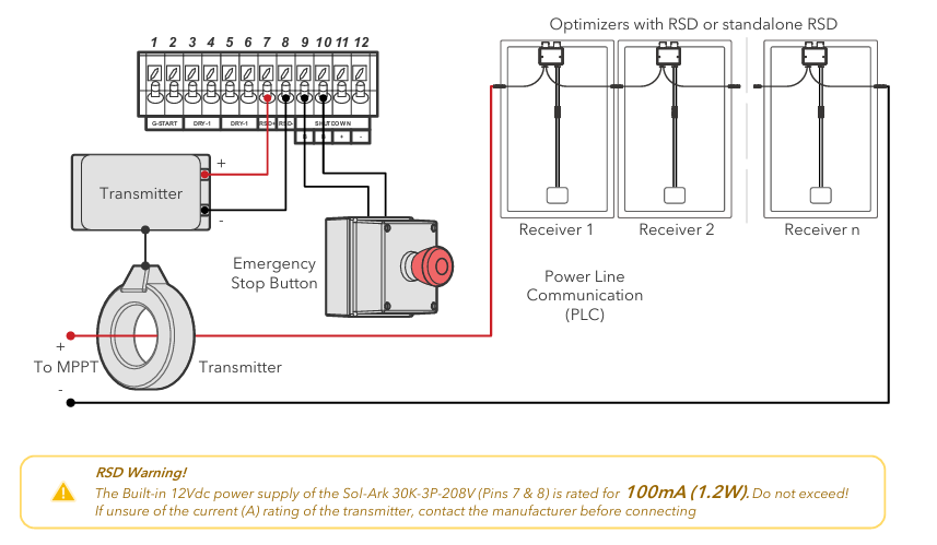
The 12V input on the RSD transmitter connects to pins 15 & 16 (12Vdc power supply) of the primary inverter.
The 15K DC power supply for rapid shutdown is only rated for 100mA (1.2W). Do not exceed!
Many RSD devices will consume too much power for this port. Contact RSD manufacturer if unsure before connecting.
Many RSD devices will consume too much power for this port. Contact RSD manufacturer if unsure before connecting.
Secure the Wifi Antenna
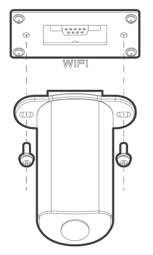
This is a good time to take a picture of the wifi antennae QR code for record keeping.
Then plug the Wi-Fi dongle into the Sol-Ark DB-9 port.
Then plug the Wi-Fi dongle into the Sol-Ark DB-9 port.
You will see solid red and green lights after a couple of minutes.
Following commissioning steps to create site in MySolArk monitoring system.
Two M4x10 screws secure the antenna housing to the inverter (included).

Be careful with this step!
It is very important to appropriately secure the screws on the antennae. Be mindful while working.
WI-FI /or Ethernet Antenna
Compatible with Wi-Fi or Ethernet connections.
Necessary for remote monitoring and software updates
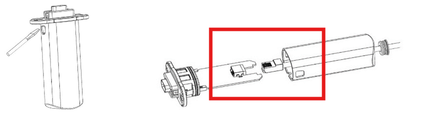
For ethernet wiring, access antenna enclosure by pressing the plastic latches with a flat screwdriver as shown in the picture.
For ethernet wiring, access antenna enclosure by pressing the plastic latches with a flat screwdriver as shown in the picture.
Insert the ethernet cable through the plastic enclosure and connect the cable to the RJ45 port.
Reassemble enclosure.
Download and Install the MySolArk App

Download and install the “MySolArk” app for android or apple smartphones. QR codes are provided below.
Create a MySolArk account
Create a MySolArk account and login at www.mysolark.com/reg
Installers should create the plant and configure the system before sharing it with the owner.
Once the plant has been created and configured, the installer can share and grant manager permissions to the owner by navigating to “My Plants” → “…” → “Share” → “Add Account”.
Before this can happen, the homeowner must create their own MySolArk so invite them to do so when possible.
Additional steps detailed in Commissioning article.
Related Articles
15K.12 Commissioning Workflow
Inverter Dipswitch Positions Inside the inverter is a dip switch. For single inverter installs, no adjustment is needed. Both switches should be down in the OFF position. For two inverters, put both dipswitches up to enable the on position. This sets ...Residential Basic Programming Guide
BASIC PROGRAMMING GUIDE SYSTEM WORK MODES AND TIME OF USE FOR SINGLE INVERTER INSTALLATIONS15K.10 Design References
Shared Battery / Grid / Gen / ports The battery, grid, gen ports must all be used for a common purpose and be combined together specific to their single function. Shared Battery Bank ALL parallel inverters MUST connect to a single battery bank. The ...15k.21 Generators
Wiring to the GEN or GRID port There are two ways to interconnect a generator to a Sol-Ark: via the GRID or GEN port. The GEN port is the easiest place to land generators onto a Sol-Ark system. Wiring to the GEN port avoids the need for an automatic ...Fortress eVault + eVault MAX 18.5
Notes: Fortress <--> Sol-Ark inverter communication switched from Modbus to CAN ~Jan 2023. Updating battery firmware across this time frame may require rewiring of the battery <--> inverter communication cable. If continuing to run in Modbus RS485, ...