15K.10 Design References
Shared Battery / Grid / Gen / ports
The battery, grid, gen ports must all be used for a common purpose and be combined together specific to their single function.
Shared Battery Bank
Shared Grid/Gen/Load ports
Stackability
Up to 12 15K inverters can be paralleled. Use new breakers when building AC combiner panels. This can be used to create very larger electrical service.
Solar on Multiple Inverters
When DC coupling, evenly distribute the solar PV arrays across multiple inverters. If one inverter must have more solar than the others, make that inverter the master inverter.
LED Interface
Home Screen
The most common use of the LCD homescreen is to tap the gear icon for settings menu, or the battery icon for the details screen.
Details Screen
The battery, grid, gen ports must all be used for a common purpose and be combined together specific to their single function.
Shared Battery Bank
ALL parallel inverters MUST connect to a single battery bank. The system will NOT operate properly if this instruction is not followed.
DO NOT use separate battery banks in parallel systems.
Shared Grid/Gen/Load ports
All AC ports must be shared among ALL parallel inverters.
For example, a generator must be connected to all inverters via AC electrical panel or other combining method. The inverter assigned as “Master” will control the two-wire start feature
Stackability
Up to 12 15K inverters can be paralleled. Use new breakers when building AC combiner panels. This can be used to create very larger electrical service.
Solar on Multiple Inverters
When DC coupling, evenly distribute the solar PV arrays across multiple inverters. If one inverter must have more solar than the others, make that inverter the master inverter.
LED Interface
DC Green → DC Solar Panels connected and providing voltage.
OFF → Minimum MPPT voltage not met, wrong polarity or no PVDC.
AC
Green → Grid is connected and providing voltage.
OFF → Grid voltage out of range or Off-Grid system.
Normal
Green → System is inverting power and has either solar AND grid /OR/ batteries.
OFF → lacks above criterion or isin fault state or passthrough mode.
Alarm
Red → Alarm state. Check the alarms menu. Home Screen→
“System Alarms”
OFF → No alarms / error codes / setting change notifications
Home Screen
The most common use of the LCD homescreen is to tap the gear icon for settings menu, or the battery icon for the details screen.
Details Screen
There is also a system details screen that can be useful for gathering real time data.
Battery temperature will measure 25°C by default if the battery sensor is not connected. DC Temperature reading can be ignored.
AC Temperature is internal to the Sol-Ark unit.
“Grid” column measures: Voltage, Current, Power and frequency of the utility grid.
If selling to the Grid, Watts = negative (-)
If buying from the Grid, Watts = positive (+)
HM: power measured by the external CT sensors. (L1, L2).
LD: power measured by the internal sensor on “GRID” terminal.
(L1, L2). Opposing “Grid” or “HM” values indicate an incorrect installation of CT.
Operating Modes
The Sol-Ark 15K-2P-N inverter will simultaneously utilize different available power sources to satisfy load demand in the electrical
service panels (essential loads panel / main service panel). The following work modes allow the user to determine how generated
power is utilized.
Keep in mind all all modes of operation are dependent upon use of CT sensors which have a (+/ - 3% error).
Grid Sell
Added to other modes of operation to enable grid sellback.
Also used with no-battery mode of operation to enable solar only well back up PV up to 15kW ac output.
Limited Power to Home + Grid Sell (Most Common)
In this most popular mode of operation, surplus energy is sold back to the grid only after the batteries meet programmable limits.
Under the grid limiter settings, "Limited Power to Home" is the standard operating mode of a Sol-Ark 15K inverter.
Limited Power to Load mode is primarily used for essential load backup panel without any desire to provide any grid side services. In this mode, power is only used to provide energy to the LOAD side of the inverter, unless the batteries are full and grid sell is enabled. In many cases, there is no functional difference between limited power to load and limited power to home mode of operation. But limited power to home is required for some modes of operation (ex. multiple inverter installations).
Time-of-Use
Picture is example only.
Time Of Use (TOU): This mode allows selective deployment of battery to accommodate a wide variety of time-variable variety of rate structures and grid charging preferences.
System energy will cover the load, including battery power at a programmable
power Power(W) rate down to a minimum % state of charge or voltage.
There are six configurable time intervals over a 24-hour period.
🗹 Charge: forces a charge from the grid to the defined percentage. Useful for ensuring a full battery before peak rates and separately for maintaining a desired battery reserve capacity overnight.
🗹 Sell: Forces a sell back to the grid. Useful when grid export rates are known to be higher than usual (California NEM3 or other net-metered peak rates). “🗹 Grid Sell” must also be enabled.
Limited Power to Home (Zero Meter)
This mode REQUIRES batteries.
This mode limits the energy produced by the inverter to satisfy the whole home demand including parallel inverters and/or non-backup panels.
In this mode, the inverter provides backup power to the LOAD terminal (essential loads panel) and also offsets grid consumption of the non-backup “GRID” terminal (main service panel).
CT sensors MUST be installed for any other these scenarios.
CT sensors measure load consumption in the main service panel to offset total load demand and prevent selling to the utility.
Useful for users that don’t sell back to the grid.
Limited Power to Load
Only recommended for single inverter off-grid systems.
This mode limits the solar production to cover “LOAD” demand (essential loads panel) exclusively.
In this mode, the system disregards loads in the main service panel and will not deliver power to the “GRID” terminal.
Limited Power to Load + Grid Sell
Only recommended for single inverter applications. Consider "Limited Power to Home" with Time-of-Use settings instead.
This mode will NOT limit solar production to “LOAD” demand. The inverter delivers power to the
“LOAD” terminal (essential loads panel) + excess power to the “GRID” terminal (main service panel AND grid), however it will ONLY track “LOAD” demand and sell excess solar up to a programmable limit. “GRID” loads cannot be measured, only the total output tthrough the “GRID” terminal.
Battery First
Default and recommended option. Sets the solar power priority of the system to charge batteries first.
Recommended for prioritizing backup, peak shaving, and extreme time-of-use rates.
Batt First ad Load First mode of operation only apply when both solar and grid/gen power are present.
Batt first will prioritize any solar production to charge the battery first. Only when the batteries are full or the battery charge value is maxed out will excess solar go into the load. This increases grid use, slightly, but makes sure the batteries are charged to 100% by solar. It is recommended for customers with time-of-use rate plans.
Load First
Sets the solar power priority of the system to cover loads demand first and deliver remaining power to batteries.
Recommended for maximizing self consumption, flat rates, and moderate time-of-use rates.
Load first will cover the full load with any solar power first, before charging the batteries. It is recommended for customers with flat rates and without beneficial solar net metering rates.
Minimum power imported from the grid. Helps avoid selling back by ensuring constant grid consumption. The
value can be set between 1 – 100W (recommended 20W).
GEN connected to GRID input
The Sol-Ark 15K is capable of detecting a generator on the GRID port of the inverter. Inverters which are significantly larger than the inverter bank or of premium quality generators may require additional design consideration (ex. 30kW+ generator on single inverter)
Specifies when a generator is connected to the “GRID” terminal.
Surge Capability
When operating in stand-alone mode (i.e. no grid) the battery bank will discharge 120% of the Max Discharge A value for a 10 second surge before the inverter faults to prevent battery damage.
Most Popular Design - No Bypass
Most customers choose not to install a grid bypass.
A grid bypass is helpful when the ESS <--> grid interconnection point fails.
Sol-Ark grid relay fuses are installer servicable parts.
It is recommended to install a grid bypass in markets where there are few solar installers available for servicing a market.
200A Bypass Switch
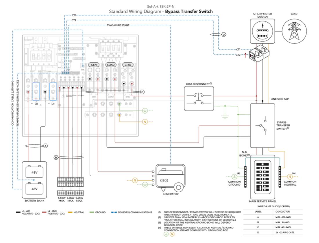
Various kinds of bypass switches can be added to the system design which allow for a full system bypass of grid electricity to the load, useful for servicing equipment.
A 200A manual bypass switch is the least costly method of adding a full service bypass to any ESS system.
Less than 200A Bypass
Interlock kits when combined with a supply side tap can provide a less costly method of providing grid bypass when servicing equipment through use of a generator interlock (as is common with a portal generator tie-in). Inspectors may have issues with the bypass needing to service the load. Design this kind of bypass carefully with AHJ approval making clear it is for servicing only. Use interlock kits provided by the panelboard manufacturer, adverised as UL67 Listed for use with identified service panels as many AHJs review this documentation closely.
Partial Backup
Connect the non-backup main service panel directly to the “GRID” input terminal. Note: This does not need to be a 200A connection per UL1741CRD PCS listing. Cables must be rated for 15kW of nameplate AC power plus any nameplate capacity of AC coupled solar. A load side connection connects to a breaker on the main service panel and only provides backup power to an essential loads panel. Energy offset power as well as grid-sellback is still provided when inverter is grid-interactive.
Meter Base Combo Panels
This is one possible way to interconnect a Sol-Ark 15K to a meter base combo. The loads would be relocated to the main service panel, or a separate subpanel tied into the GEN port of the inverter. The image also suggests two ways to add a grid bypass to the system.
Two Inverter Systems
Two Inverter Systems
It isn't always necessary to combine inverters together with electrical subpanels. For example, an AC disconnects might have double lugs which could be used to combine two inverters.
The systems might land directly onto a 400 amp main lug only panel, or a power distribution block could be used to power two 200 amp sub panels with a combined feed.
Size the AC disconnected based on the size of the utility service.
3 inverters
Here is an example with three inverters. Sol-Arks are commonly used to backup very large 120/240V split phase residential systems.
Here is an example with three inverters. Sol-Arks are commonly used to backup very large 120/240V split phase residential systems.
Related Articles
15K.12 Commissioning Workflow
Inverter Dipswitch Positions Inside the inverter is a dip switch. For single inverter installs, no adjustment is needed. Both switches should be down in the OFF position. For two inverters, put both dipswitches up to enable the on position. This sets ...15K.11 Installation Workflow
Inspect Shipment Upon delivery of materials, photograph the inverter box, showing any damage or list any missing components. If damage or missing parts, immediately call +1 (972) 575-8875. Other Useful Site Photographs Transmitter Dongle Serial ...15K.13 Inverter Troubleshooting
LED Display RED LED: Device communication indicator. GREEN LED: MySolArk server communication indicator. When both the red and green LEDs on the Wi-Fi dongle are consistently illuminated, it signifies normal operation, while flashing indicates data ...15k.21 Generators
Wiring to the GEN or GRID port There are two ways to interconnect a generator to a Sol-Ark: via the GRID or GEN port. The GEN port is the easiest place to land generators onto a Sol-Ark system. Wiring to the GEN port avoids the need for an automatic ...Residential Basic Programming Guide
BASIC PROGRAMMING GUIDE SYSTEM WORK MODES AND TIME OF USE FOR SINGLE INVERTER INSTALLATIONS