15K.12 Commissioning Workflow
Inverter Dipswitch Positions
Inside the inverter is a dip switch.
For single inverter installs, no adjustment is needed. Both switches should be down in the OFF position.
For two inverters, put both dipswitches up to enable the on position. This sets a resistor supporting communication between inverters.
For three or more inverters, follow the patten shown.
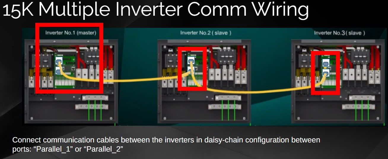
Inverter Communication Wiring
The inverter-to-inverter communication ports are cross-compatible, so technically speaking, the order doesn't matter which ports are used. "Parallel_1 and Parallel_2" ports on the inverter are used for parallel inverter communication. However, even though technically either port works, if you follow the displayed communication wiring arrangement, then it will be obvious if the inverter is wired a master inverter or a slave inverter.
Confirm battery voltage to inverter.
1. Turn ON internal switches of the batteries Check the voltage of the battery bank A. Voltage of the battery must be between 43VDC - 63VDC.
2. Verify that the voltage of the battery bank at the Sol-Ark terminals is adequate.
3. DO NOT open battery disconnect if current is flowing in or out of the battery.
Confirm PV Voltage if sunny.
Check the voltage of each PV input circuit. Input voltage must be below 500V and above 125V startup voltage for solar to function.
Verify polarity in each PV string. Backward polarity will measure 0Vdc by the Sol-Ark and will cause long term damage. E. PV alone turns LCD screen only. Inverter requires grid and/or batteries to operate, otherwise an “OFF” message will appear. F. PV DC disconnect switch on the side of the inverter will turn the PV ON or OFF.
Check Grid Voltage
Use the “GRID” terminals to measure AC voltage with a multimeter.
Measure line (L) to neutral (N) voltages on “GRID” terminals. Ensure 120VAC on all phases.
Measure line (L) to line (L) voltages on “GRID” terminals. Ensure 240VAC. (If voltage reading is close to 220V or 210V, verify if grid is
single-phase or three-phase instead).
Verify that voltage between Neutral and Ground is 0VAC.
Verify that voltage between “GRID” L1 and “LOAD” L1 is 0V. Do the same for L2.
15K Power Cycle Sequence
Turn ON the battery breaker(s). Power Up The Batteries
Press the push button on. The pushbutton will remain inward while on.
Screen Indicator Check
Wait for the “Normal” LED indicator to turn on. This may take a few minutes.
Turn Solar On
Turn ON the PV DC disconnect switch. Wait for “DC” LED indicator to turn on.
Turn Grid On
Turn ON the external “GRID” disconnect. Wait for “AC” LED indicator to turn on.
Turn Load On
Turn ON the internal “LOAD” breaker and then any external “GEN” breakers.

Power Off Sequence
The Power Off sequence is the Power On sequence in reverse:
1. Gen disconnect open
2. Load breaker open
3. Grid disconnect open
4. Solar disconnect open
5. Inverter push button off
6. Battery power off
7. Battery breaker open
Grid Setup Parameters
In most cases, select grid mode to UL1741SB, 60Hz, and 120/240V Split Phase.
UL1741SB: Applies UL 1741SB grid interconnection requirements and standards.
General Standard: Enables grid frequency and voltage adjustments. Useful for off-grid applications with backup generators).
UL1741 & IEEE1547: Applies UL 1741 and IEEE 1547 grid interconnection requirements and standards.
Otherwise adjust as instructed.
Caution: When installing in multi-tenant complexes, verify if split-phase or 2 legs of 3 phase power.
Grid Reconnect Time: The amount of time in seconds the inverter will wait before reconnecting to the grid.
Parallel Tab / RGM Setup
See multiple inverter installation workflow for commissioning multiple inverter systems.
See no battery workflow when installing inverters with no batteries.
See 3rd party integration workflow when adding modbus devices to the inverter (solar assistant, AcumenEMS, etc)
Pre-commission batteries
Warning: Do not attempt to commission and/or charge batteries below 32F / 0C
If batteries have been subject to freezing tempertures, bring to above 32F / 0C for at least 24 hours before commissioning batteries.
Confirm battery <--> Inverter polarity wiring
Keep load, solar, grid, or generator switches in the OFF position.
Turn on one battery module and confirm correct polarity on the Sol-Ark DC battery terminals, using a multi-meter.
Confirm battery voltage range is within 0.5V of neighbor batteries
Keep the Sol-Ark battery disconnect in the off position.
Turn ON each battery modules one at a time, taking note of voltage. Be sure to turn OFF the previous battery before turning on the next battery module.
If battery voltages are far apart from each other, the batteries may not accept a charge/discharge. Try to bring the total battery bank voltage to within a 0.5V range of each other before commissioning. Example: selectively turn on groupings of batteries to self-balance. If you cannot balance the battery bank, use the inverter or an external charger to charge the lower voltage batteries to the higher voltage battery group. This may be a multi-step process.
Programming Amperage Inverter Settings
Confirm or adjust max 275A
Confirm or adjust max 275A
If unsure on system parameters during commissioning, a good first step is to restrict the Max A Charge and Discharge amperage to 50A and then proceed with setup, readjusting max amperage after confirming battery communication.
Max A Charge/Discharge: Sets the maximum charge and discharge current (A) rate from the batteries → 275A max allowed.
For multiple inverter installations, amperage values programmed into the inverter LCD screen are not cumulative. The only cumulative value is battery ampacity.
Finalizing Max Ampacity
Finalizing Max Ampacity
Only keep at 275A if confident the conductors are sized per NEC for 275A continuous. Otherwise program the NEC compliant amperage and consider locking user out of settings adjustment. It is not unusual to set charge rates to a lower amount than discharge rates if fine tuning system performance for battery longevity.
May be controlled by the battery if battery <--> inverter communication is enabled.
Set volt charge parameters if battery comms fail
Put battery into "Use Batt V Charge" mode and program all voltage related set points on the charge and discharge tab provided by the battery manufacturer.
Optionally skip this step if establishing communication between the battery BMS and the inverter. See 48V battery workflows.
Use Batt V Charged: Displays battery charge in terms of voltage.
Set manufacturer Float, Absorption, and Equalization voltages.
Float V: Lower steady voltage at which the battery is maintained after being fully charged.
Absorption V: Constant voltage used to charge the battery.
Absorption will stop at 98% of the capacity of the battery bank and then drop to the Float setpoint.
Example: A 400Ah battery will stop charge reaching 392Ah.
Percent vs. Volt Mode
After setting the voltage mode, adjust the inverter to "Use Batt % Charge" and program the inverter % settings on the charge and discharge tab.
Most customers prefer percent mode of operation. It is appropriate to operate in voltage mode when:
1) instructed by the installer or support team familiar with battery voltage settings
2) when adding new batteries to old systems for a couple months of post-commissioning operation
Batteries with BMS mode of operation will display % rather than voltage to the customer.
Use Batt % Charged: Displays battery charge in terms of %.
The inverter uses algorithms measuring power in and out to estimate a true value for state-of-charge %. It compensates for aging batteries.
Discharge Tab
The discharge tab will flip between percentage and voltage based on what is programed in the Batt tab.
The levels are linked - you may not adjust one above or below another.
Shutdown: load will shut down to protect battery from deep discharge until sun up (red battery on LCD home screen).
Low Batt: TOU stopping point and alert trigger. (yellow battery on the LCD home screen).
Restart: After shutdown, load will not return until batteries are recharged to this point.
Batt Resistance: Used in % SOC batt calculations. More important for lead acid batteries.
Batt Charge Efficiency: Used in % SOC batt calculations.
Empty V: Associates this voltage to 0% state-of-charge.
BMS_Err_Stop: Enables system stop when loss of bms communication (not recommended).
Equalization
Set “Hours” to zero to disable equalization. See lead acid battery installation for lead acid instructions.
Equalization V: Voltage that the system uses to generate a calculated overcharge, utilizing a higher voltage or equal to the absorption to remove the generation of sulfates in batteries. Used to balance internal cells. Most Lithium batteries do not need to equalize.
Days: The period between equalization cycles.
Hours: The period taken to equalize batteries.
Activate Battery + TEMPCO
Turn on the activate battery setting. This setting helps with battery energy efficiency.
See "no battery" workflow if not installing a battery.
TEMPCO: Only programmed wth lead acid batteries. Lithium batteries do not require a TEMPCO setting (-0 m/V/C/Cell).
Battery Capacity
Battery capacity Is commonly auto-programmed when installing battery <--> inverter communication.
Proceed to next step if inverter will communicate with battery. Otherwise program the battery ampacity based on battery manufacturer instructions.
See lead acid battery workflow for specific instructions.
Batt Capacity: Specifies the capacity of the battery bank. Value expressed in Amp Hour (Ah).
Batteries in series → Voltage adds up (V).
Batteries in parallel → Capacity adds up (Ah).
Battery <--> Inverter Communication
After completing battery installation workflows, confirm any battery communication.
BMS Lithium Batt: Allows closed-loop communication with our tested batteries included in our “Battery Integration Guide”. Refer to www.sol-ark.com/battery-partners for complete list of compatible batteries. In the pictured example, the battery uses Sol-Ark BMS protocol 00. This number will depend upon battery manufacturer. See battery partner commissioning instructions.
Go to the Lithium Battery Info Menu
To confirm battery communication, enable BMS lithium battery mode and then check the Lithium Battery Information menu.
Confirm battery communication
The display of any data (i.e. not just zeros) shows battery <--> inverter communication, sometimes called "closed loop" communication.
Battery communication will program and control many inverter settings.
Seasonal Controller / Time Tab
IMPORTANT
The seasonals for the seasonal controller MUST BE PROGRAMMED ON SITE.
Go to Basic Setup -> Time tab and program the start and stop dates for season 1, 2, and 3.
Disable Time Sync and Adjust Date to Season 1
Manually adjust the date to within each season in order to program each season.
1. Disable Time Sync
2. Adjust the inverter date to any date within Season 1.
3. Program TOU + demand threshold settings.
4. Repeat for Season 2 and 3.
Time-of-Use Settings
Select Grid Limiter to enable the TOU settings.
Set power level to 15kW or throttle if desired.
Each season has six time slots.
Order time slots starting at 12:00AM and ending at to 11:59 PM.
Suggested time slots:
Early Morning
After Sun Rise
1 Hour Before Peak Rate Start
Peak Rate Start
Peak Rate End
Late Night
Change to AM/PM by going to the Basic Setup menu → Display.
The Charge box will force a charge from the grid if enabled.
Use to provide a grid maintenance charge at 20%, or to charge to 100% before Peak Rates or when Peak Shaving.
If no power source on the GRID port is available, TOU settings will be ignored.
Adjust Date to Season 2 and 3.
When done programming Season 1 time of use parameters and/or peak shaving threshold, adjust the date to season 2.
Repeat for Season 3.
Enable Time Sync
Don't forget to ennable time sync at the end.
Example TOU Setting
In this example time-of-use configuration the battery is kept at a 20% state of charge overnight. At noon, if the battery needs to be charged, solar will charge the batteries to 100% rather than prioritizing the load. This will ensure the batteries are full by the time the 2PM TOU peak rate starts.
At 2PM, the battery is discharged into the load until it hits 20% state of charge. If during this time, the battery is charged to 100%, it will sell back any excess solar to the grid.
At 10PM, the grid maintains the batteries at a 20% state of charge overnight.
Using TOU for adjustable reserve capacity to keep above Start %
The reserve capacity programmed into the TOU settings should be set above the start percentage in the Battery Setup Menu. This will allow the battery use to cut out without triggering a full grid or generator recharge.
Remember some of these settings are interlinked. For Example the start percentage cannot be lower than the shutdown percentage etc.
Exempt Weekends from Seasonal Controls
Press the setup button to disable the time of use settings on certain days of the week or only to certain seasons. This is not a frequently used setting.
Most cases will want TOU settings enabled for every season and day of the week.
Battery Only Setup
Battery Only installations should charge from the grid off peak and discharge to the load during peak times (do not enable grid sell).
Peak Shaving Setup
Peak shaving installations should have all charge times go to 100% full.
When the peak shaving threshold is exceeded, the inverter will overide these settings to discharge the battery. The battery will only charge when the peak demand theshold is exceeded.
The Sol-Ark supplies power from the batteries whenever the “Power” threshold is met.
Grid-Peak Shaving: Sets a “GRID” consumption threshold that allows use of battery backup power during peak demand.
External CT sensors are required. Peak shaving can be used on a generator provided it is wired to the “GRID” terminal.
Settings Lockout / Factor Reset Tab
The factory rest tab can be also be used to lock out system settings.
You may lockout the user from adjusting system settings in this menu, amongst other items.
Download and install the “MySolArk” app
if you have not already done so. Then login.
Select Create a Plant
In the upper corner of the screen
Scan QR Code
A photo of this QR code was captured during the installation stage of this project.
Find the QR code on the wifi dongle and scan to create a site or type the serial and key in manually.
Take note of the serial number and key.
Plant information
Enter in as much plant information as possible including plant name.
Include installer name.
Enter plant name in this app as well.
Configure Network
Turn inverter ON to power dongle
You will be asked to connect to the wifi signal broadcast from the inverter.
Confirm Transmitter
The app will display the serial number of the wifi dongle you are connected to.
Wifi Password
A wifi password is required to utilizie wifi connection.
The password is 12345678
Connect to Site Wifi
The MySolArk app will then prompt you to connect to the wifi network of the site, establishing internet connection to the device from site internet.
Access Wifi Settings
NOTE: The Wi-Fi configuration tool can be accessed at any other time by tapping “Me” at the bottom right corner, then “Tools” and finally “Wi-Fi configuration”. STEP 3 shows an alternative method of connecting the Wi-Fi dongle to a local network through an IP address.
Configure Wi-Fi Network Through an IP Address
On a Smart Phone or Computer connect to the EAP-##### network. You can do this by going to: Settings → Wi-Fi → Select the EAP-##### network → Password= 12345678. The EAP-##### network contains the last 5 digits of the Dongle Serial Number. You can find this number on the label. C. A message such as “Connected without internet” will appear once the device is connected to the EAP
Do not connect to inverter wifi for internet access
NOTE: The Wi-Fi dongle does NOT provide internet access. It needs an external internet provider to connect to. The dongle is compatible with Wi-Fi signal broadcasted at 2.4 GHz (it is not possible to use 5 GHz)
Connecting to local wifi for inverter commissioning
Scroll down to the "Wlan Connection" section and press the “Scan” button to scan for local Wi-Fi networks. G. Nearby Wi-Fi networks will appear. Select the local network you would like to connect to, input your credentials, and tap “Connect”. H. Once connected, a “Connection Successful” message will appear. Press the “Save” button next to “Scan” to save settings.
Wait a moment (~5 minutes). The dongle will then connect to the Wi-Fi network and will now have access to MySolArk.
NOTE: DO NOT connect to the EAP-##### network as that is the Wi-Fi dongle itself. The device does not provide internet access.
Success
If the connection is a success, you will see the following LED indicators. o SOLID : Connected and powered by the Sol-Ark inverter. o SOLID : Connected to the router and to MySolArk.
Related Articles
15K.10 Design References
Shared Battery / Grid / Gen / ports The battery, grid, gen ports must all be used for a common purpose and be combined together specific to their single function. Shared Battery Bank ALL parallel inverters MUST connect to a single battery bank. The ...15K.11 Installation Workflow
Inspect Shipment Upon delivery of materials, photograph the inverter box, showing any damage or list any missing components. If damage or missing parts, immediately call +1 (972) 575-8875. Other Useful Site Photographs Transmitter Dongle Serial ...15K.13 Inverter Troubleshooting
LED Display RED LED: Device communication indicator. GREEN LED: MySolArk server communication indicator. When both the red and green LEDs on the Wi-Fi dongle are consistently illuminated, it signifies normal operation, while flashing indicates data ...15k.21 Generators
Wiring to the GEN or GRID port There are two ways to interconnect a generator to a Sol-Ark: via the GRID or GEN port. The GEN port is the easiest place to land generators onto a Sol-Ark system. Wiring to the GEN port avoids the need for an automatic ...Residential Basic Programming Guide
BASIC PROGRAMMING GUIDE SYSTEM WORK MODES AND TIME OF USE FOR SINGLE INVERTER INSTALLATIONS