15K.13 Inverter Troubleshooting
LED Display
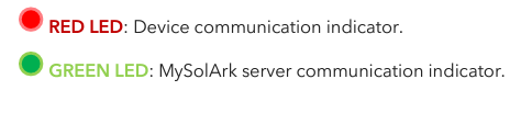
RED LED: Device communication indicator.
RED LED: Device communication indicator.
GREEN LED: MySolArk server communication indicator.
When both the red and green LEDs on the Wi-Fi dongle are consistently illuminated, it signifies normal operation, while flashing indicates data transmission.
“Normal” LED indicator is not on
- Sol-Ark is in pass-through-only mode, only a Grid connection
- Not fully energized (DC Solar panels AND Grid or just batteries)
- In alarm state. Sol-Ark is not working correctly (Call technical support +1 (972) 575-8875 Ext. 2)
The “Alarm” LED indicator is on
- Check the system alarms menu to identify the alarm
LCD is not powering on
LCD will power on with one power source (grid, solar, or battery)
Confirm power supply and press the power button, touch screen, and navigation buttons .
Why is the LCD screen still on when the power button is off?
The screen can power up with solar is present but will not update unless the inverter push button is powered on.
Color Touchscreen is Frozen
- Press and hold the escape button [◄] for 7-10 seconds
- Perform a power cycle sequence in case the above suggestion does not work.
System is beeping
- Check the System Alarms menu to see which alarm has been triggered. Most alarms will self-reset - Do a Power Cycle as described in section 2.12 “Power Cycle Sequence”
Clear Arc Fault
In the basic setup menu, advanced tab.
Clear Arc Fault: Command to clear an Arc Fault. It must be executed manually every time the system detects an F63 Arc Fault alarm.
Solar Arc Fault ON: Enables Arc fault detection algorithm on the MPPTs.
System Has Restarted
Occurs when the system has overloaded, battery voltage has surpassed 63V - There was a Software update
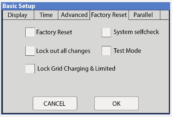
Factory Reset
Notify technical support when performing a factory reset.
CT Autodetect
AC coupled inverters need to be OFF during the detection test.
REQUIRES batteries, 120/240V only, no active AC-couped solar. Otherwise a factory reset of the Sol-Ark must be performed. Not compatible with peak shaving mode of operation.
Basic Setup → Advanced → 🗹 Auto detect Home Limit Sensors
Wait at least 10 to 15 seconds while the inverter performs the test. The inverter will alternate the current distribution in all lines, determining the correct orientation of the sensor. Zero Export Power is set to 20W or greater.
On “Limited power to Home” mode (no Grid Sell), HM values will read close to zero (0).
Power from the grid will display positive (+) HM values, Power to the grid displays negative (-) HM values.
Error Codes
F1 DC_Inversed_Failure
If you have parallel systems and turn one system off, you will get this notification. NOT a fault.
Troubleshooting the F01 Fault on an Inverter
Step 1: Confirm the Fault
- Check if the F01 alarm is currently activated on the inverter.
- Yes: Proceed to Step 2.
- No: The fault is not active. No further action is needed.
Step 2: Count the Fault Triggers
- Determine if the F01 fault has been triggered 5 times on the inverter.
- Yes: Perform a manual power cycle on the inverter and verify if the alarm reactivates.
- If alarm reactivates: Proceed to Step 3.
- If alarm does not reactivate: Fault is resolved.
- No: Proceed to Step 3.
Step 3: Check for Parallel Setup
- Is the inverter operating in parallel with others?
- Yes: Continue to Step 4.
- No: Proceed to Step 6.
Step 4: Identify Related Issues
- If parallel, check if any slave inverters have shut down.
- Yes: Fault may have been triggered due to one or more slave inverters in the installation shutting down while the master inverter is still energized.
- No: Check for any other faults indicated in MySolArk or inverter system alarm logs.
- If other alarms display around the time period of the F01 alarm: Troubleshoot the additional fault first, as F01 may be a secondary notification.
- No: Continue to Step 5.
Step 5: Check for Scrambled Settings
- Are there scrambled settings on the inverter?
- Yes: Reconfigure the inverter settings, perform a manual power cycle, and check if the fault reoccurs.
- If fault reoccurs: Consult assistance with technical support at 972-575-8875 Ext. 2.
- If fault does not reoccurs: Fault is resolved.
- No: Skip to Step 6.
Step 6: Reverse Polarity Check
- Confirm if the F01 fault relates to DC reverse polarity on PV inputs. Using a voltmeter you can test the polarity of the PV strings going into the PV1, PV2, or PV3 inputs of the Sol-Ark Inverter.
- If polarity is incorrect: Inspect and correct the layout of the solar array.
- Ensure positives connect to positives and negatives to negatives from the inverter to the panels.
- If polarity is correct: Continue to Step 7.
Step 7: Voltage and Firmware Check
- Verify that the voltage of PV modules are within the specifications of the Sol-Ark inverter. If you are unsure of the specifications of your Sol-Ark inverter, you can refer to the spec sheet of your specific inverter.
- If voltages are within specs of the inverter: Ensure the inverter firmware is up to date.
- If firmware is up to date: Continue to Step 8.
- If firmware is not up to date: Update the firmware and check if alarm triggers again.
- If voltages are not within specs of the inverter: Adjust the PV array to meet voltage specifications of the inverter. You can refer to our solar sizing tool for assistance with the layout of the PV array.
Step 8: Final Resolution
- If the fault persists after completing these steps, contact technical support at 972-575-8875 Ext. 2.
F8 GFDI_Relay_Failure
Check for continuity on the inverter's neutral and ground. Ensure there is only ONE neutral-to-ground bond in the system. Current Leakage from inverter AC output to Ground, check Ground and neutral are connected at the main panel.
F13 Grid_Mode_change
It can happen when not using batteries or if Grid Input settings are changed. This is a notification, NOT a fault. If you switch from No Batt to Battery mode, power the system down completely to restart. F15 AC_OverCurr_Failure It is usually caused by Loads too large for the inverter. If Off-Grid, the battery discharge Amps are programmed too low. Overloads can result in F15, F18, F20, or F26.
F16 GFCI_Failure Ground fault.
Check PV+ or PV- wiring (which must be ungrounded). Exposed PV conductors + rain can also cause. Check that the neutral line and Ground are not double-bonded (common with portable generators).
F18 Tz_AC_OverCurr_Fault
Overloaded the Load Output (reduce loads) or overloaded a generator (reduce Gen Start A). Wiring Short on the AC Side can also cause this error.
Overloads can result in F15, F18, F20, or F26.
F20 Tz_Dc_OverCurr_Fault
It is typically caused by DC current from the battery that is too large (ex: 4 Ton AC Unit) or too much PV current (3 or more strings in parallel). Overloads can result in F15, F18, F20, or F26. F22 Tz_EmergStop_Fault Initiated Emergency Stop; see sensor pinout table. F24 DC_Insulation_Fault An exposed PV conductor combined with moisture is faulting (can cause F16, F24, and F26). F25 DC_Feedback_Fault No battery connection to the Inverter and Activate Battery is enabled. Disable Activate Battery in settings while no battery is connected.
F26 BusUnbalance_Fault
Too much load on one leg (L1 or L2) vs. the other leg or DC loads on the AC output when Off-Grid. Grounded PV+/- wire can cause F20, F23, or F26. F29 Parallel_CANBus_Fault Usually, a communication error for parallel systems. Check cables, and MODBUS addresses.
F31 Soft_Start_Failed
Soft Start of the large motor failed. F34 AC_Overload_Fault AC Overload or load shorted. Reduce heavy loads. F35 AC_NoUtility_Fault Grid connection lost. F37 DCLLC_Soft_Over_Cur Software DC overcurrent. F39 DCLLC_Over_Current Hardware DC overcurrent.
F40 Batt_Over_Current
Batteries exceeded their current discharge limit. F41 Parallel_System_Stop_Fault If one system faults in parallel, this normal fault will register on the other units as they disconnect from the grid. F45 AC_UV_OverVolt_Fault Grid under voltage causes a disconnect. This will self-reset when the grid stabilizes.
F46 Battery_Backup_Fault
Cannot communicate with other parallel systems. Check Master = 1, Slaves = 2-9 and that ethernet are connected.
F47 AC_OverFreq_Fault Grid
over Frequency (common in power outages) causes disconnect. Will self-reset when grid stabilizes.
F48 AC_UnderFreq_Fault Grid
under Frequency (common in power outages) causes a disconnect. Will self-reset when grid stabilizes.
F55 DC_VoltHigh_Fault
PV may be higher than 500V. Battery voltage should not be above 59V or 63V (depending on the model).
F56 DC_VoltLow_Fault
Batteries are overly discharged, the inverter is Off-Grid and exceeded the programmed batt discharge current by 20%, or Lithium BMS has shut down. If battery settings are incorrect, this can also happen.
F58 BMS_Communication Fault
Sol-Ark is programmed to BMS Lithium Battery Mode but cannot communicate with a BMS. BMS_Err_Stop is enabled, but cannot communicate with a battery BMS s
F60 Gen_Volt_or_Fre_Fault
Generator Voltage or Frequency went outside the allowable range.
F61 Button_Manual_OFF
The parallel Slave system turned off without turning off the Master.
F63 Arc_Fault
It can be a poor PV connector / Connection. Or sometimes a false alarm due to powerful lighting storms.
F64 Heatsink_HighTemp_Fault
Check that the built-in fans are running; the ambient temperature may be too high. Ensure proper clearance.
AC Overload Fault or Bus Unbalance Fault
AC Overload Fault or Bus Unbalance Fault
- Check Transfer Switch/Subpanel wiring - Check for large loads that consume more than the inverter rating
The system connects to grid and quickly disconnects
Verify Neutral wire connection (0Vac referenced to GND) - Check the programmed frequency, and verify the Sol-Ark measures 120V between L and N - If the system is overloading: verify that proper phase sequence between “GRID” and “LOAD” terminals
Grid symbol on the home screen is yellow
- Grid parameters are out of specified operating range - There is a grid outage and there is no voltage on the “GRID” terminal - System is Off-Grid
Grid HM value is negative when it should be positive
Limiter Sensors are backwards, L1/L2 sensors are swapped, or incorrectly wired.
Put inverter in Limited to Home mode and execute "Auto Learn Home Limit Sensors" command in the Basic Setup Advanced Tab menu.
Do not use autocalibration when AC coupled solar is active.
Do not use autocalibration for three phase or peak shaving applications.
If the Sol-Ark screen shows a “Grid Phase Wrong” message, it means there is a phasing issue in the wiring. If left unchecked it may cause overload faults and DAMAGE. See section 5.3 “Three-Phase Systems”
The system does not keep batteries charged
- Verify there is proper communication between the Sol-Ark and the battery. : → Li-Batt Info - Verify proper Charge and Voltage settings according to battery manufacturer and battery bank arrangement
Battery cable sparks when connected
If applicable, flip the built-in breakers of the battery bank before connecting or disconnecting batteries.
Batteries were connected backwards
- System will be damaged, and warranty will be lost
The battery is below the empty voltage or in over voltage.
Please refer to battery manufacturer instructions for recovering deep discharged batteries. Confirm all batteries are working before leaving site by observing amperage flowing in or out of each battery module.
Battery symbol on the home screen is yellow
- The battery is low, or the charge/discharge current is close to the programmed limit
The Batt SOC% is not reaching 100%
- The Sol-Ark might be in the calibration phase and estimating the battery SOC. We suggest waiting three full days to let the unit go through the 4-stage charging curve to converge to an accurate % - If the suggestion above does not work, you can re-adjust the battery capacity under “Battery Setup” → “Batt Capacity” to restart the calibration process
Auto Gen-Start is not working
- Make sure the generator has a compatible Two-Wire - Verify adequate connection to the Sol-Ark auto-start input pins
Generator setup is reading 0Hz
Generator is operating at a frequency outside the permissible range. Select " General Standard " grid mode. Widen the frequency range to 55Hz-65Hz as described in section 2.5 “Integrating a Generator”
Panels are connected, but “DC” LED indicator is not on
Minimum starting voltage is 125V. Voltage must be above 125V and below 500V - Wrong polarity. Check string polarity on MPPT - PV DC disconnect is not on the ON position
Panels are not producing
- Check for proper wiring on all solar panel connections
- Turn PV disconnect "ON"
- Check that the PV input voltage is not greater than 500V
- If the system measures 0V even when PV DC disconnect is ON, polarity might be wrong. Check PV polarity
Panels are not producing much power
Your batteries are charged and is limited to house loads; you can test Grid Sell to verify.
DC Overload Fault
- Check PV voltage. Ensure no more than 500V - Make sure you have not wired more than two (2) solar strings in parallel per MPPT
Changes to Grid Settings
Using the LED screen, change “Grid Mode” to “General Standard”, and change “Grid Reconnect Time” to 30 seconds.
Exercising the Generator
CT Sensors Off Grid
Adjusting Generator Behavior
Enable time-of-Use settings to generator behavior. * Ex. Charge from 25% to 80% * Avoid Quiet Hours
Generator in Off Grid
Panels are not producing much power
Your batteries are charged and is limited to house loads; you can test Grid Sell to verify.
DC Overload Fault
- Check PV voltage. Ensure no more than 500V - Make sure you have not wired more than two (2) solar strings in parallel per MPPT
Changes to Grid Settings
Using the LED screen, change “Grid Mode” to “General Standard”, and change “Grid Reconnect Time” to 30 seconds.
Exercising the Generator
Auto Gen-Start activates at “Start V / %” value and charges batteries to approximately 95% capacity.
An exercise function will turn on the generator once a week on Monday mornings at 8 AM for 20 min by default. This exercise is to maintain the internal generator batteries.
CT Sensors Off Grid
Limit sensors (CTs) are not required for completely off-grid installations unless using “Grid Peak Shaving” for a generator connected to the “GRID” terminal.
Connecting generators to the “GRID” terminal is recommended to facilitate the integration “GEN” connected service panel. This setup enables the utilization of the “Smart Load” function. 3. There is no need for a transfer switch. Connect the “LOAD” output to the main panel.
DO NOT use “Grid Sell” mode when Off-Grid. ONLY “Limited Power to Load” (default).
Adjusting Generator Behavior
Enable time-of-Use settings to generator behavior. * Ex. Charge from 25% to 80% * Avoid Quiet Hours
Generator in Off Grid
When using a Generator in an Off-Grid situation, it is recommended to change the “Grid Mode” to “General Standard” and a “Grid Reconnect Time” to 30 seconds. See section 2.5 “Integrating a Generator” for detailed instructions. 6. The Auto Gen-Start activates when the battery voltage (V) or percentage (%) reaches the pre-set “Start V / %” value. Subsequently, the generator will sustain the charging process until the batteries reach approximately 95% capacity. This is a non-modifiable upper limit unless Time of Use is enabled and programmed. o An exercise function will turn on the generator once a week on Monday mornings at 8 AM for 20 min by default. This exercise is to maintain the internal generator batteries.
Related Articles
15K.10 Design References
Shared Battery / Grid / Gen / ports The battery, grid, gen ports must all be used for a common purpose and be combined together specific to their single function. Shared Battery Bank ALL parallel inverters MUST connect to a single battery bank. The ...Residential Basic Programming Guide
BASIC PROGRAMMING GUIDE SYSTEM WORK MODES AND TIME OF USE FOR SINGLE INVERTER INSTALLATIONS15K.12 Commissioning Workflow
Inverter Dipswitch Positions Inside the inverter is a dip switch. For single inverter installs, no adjustment is needed. Both switches should be down in the OFF position. For two inverters, put both dipswitches up to enable the on position. This sets ...15k.21 Generators
Wiring to the GEN or GRID port There are two ways to interconnect a generator to a Sol-Ark: via the GRID or GEN port. The GEN port is the easiest place to land generators onto a Sol-Ark system. Wiring to the GEN port avoids the need for an automatic ...15K.11 Installation Workflow
Inspect Shipment Upon delivery of materials, photograph the inverter box, showing any damage or list any missing components. If damage or missing parts, immediately call +1 (972) 575-8875. Other Useful Site Photographs Transmitter Dongle Serial ...